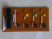
This board provides 4 buttons connected to Raspberry Pi GPIO to act as inputs, and 4 LEDs connected to GPIO to act as outputs. Very simple!

The motivation for the creation of this project was to try to do something with Raspberry Pi at our local CoderDojo which was different to what could be done with hardware that the “ninjas” had already been exposed to.
The ability to easily interface with hardware is what really sets the Raspberry Pi apart. Scratch, python, etc., are all available on the laptops which they are already using – so I thought this would show them a different side to programming.
Why DIY?
There are several add-on boards available for the Raspberry Pi which have similar functions, so you are entitled to ask why I went back to basics and built my own rather than just buying one of those already available.
I suppose the main reason is that I just wanted to build my own, I had the components available, and it was quicker than ordering something and waiting for it to arrive. Retrospectively, though, using these at CoderDojo and seeing the realisation in the ninjas’ faces that this is something which I made, rather than bought, and that therefore they could learn to make them themselves, ultimately, has added a new motivation which I hadn’t anticipated.
In general, so far, given the age of the ninjas at our local dojo, it has been parents asking “how can I make one of those?” – but hopefully this is an experience they will share with their kids.
So, what follows is a set of instructions to allow you to build one of these boards yourself – if you’ve never soldered before, you may find this a little challenging. It could be worth searching youtube for a soldering tutorial and practising a little first but the components for this project are inexpensive – if it all goes wrong, you won’t have lost much!
I would suggest reading through this post in full, and if you have any questions or concerns, ask in the comments, and I will update the post if I can offer any useful advice before you start!
Alternatives to Building Your Own
Given that this is a somewhat challenging project, it is worth noting that there are some decent alternatives out there, so you could select one of these depending on your level of ability.
Firstly, I heartily recommend the CamJam EduKit. It contains a solderless breadboard, one switch, three LEDs and a buzzer (plus resistors to current-limit the LEDs). There are currently 6 worksheets available (at time of writing) with more to come. We have a couple of these at our dojo and they’re an excellent introduction to hardware tinkering and python.
Also, if you want something more permanent, there are a couple of kits available from 4tronix (and no doubt other retailers) which look very interesting. The PiDie GPIO, which comes as a kit for £8, and ModMyPi’s PushYourPi which is only £6.65. Each of these boards has its buttons and LEDs wired directly to the GPIO port, making software development simple and giving maximum flexibility in the software tools which can be used. These are both kits which will require soldering, but construction will be easier than building my board, which requires stripboard tracks to be cut, and requires concentration to ensure components are placed correctly before soldering.
OK, so that’s the alternatives dealt with, if you’re still determined to press ahead, let’s get on with it!
What do I need?
Tools
- A soldering iron
- Some solder
- A pair of side cutters
- Stanley knife, or scalpel with stiff blade
- Spot face cutter or 3mm drill bit
- Wire strippers
Components
- A piece of stripboard (also called veroboard), e.g. Maplin: JP47B
- 4 LEDs, of various colours, e.g. Maplin: N73KG (Red) – though these are expensive compared to alternatives available on ebay if you’re confident in what you’re buying!
- 4 PCB switches, e.g. Maplin KR89W
- Resistors (1/4W rated)
- 4x 470Ω
- 4x 10k
- I would recommend buying a pack of common values, e.g. an “E12” resistor series pack, Maplin FA08J – you’ll probably need some again in future, and they’re not expensive.
- Connector – 26-pin IDC bump-polarised male – e.g. Maplin N97NQ
- Ribbon cable – 26-way IDC – e.g. Maplin N96NQ
- Some equipment wire – e.g. Maplin FA26D
Note that in general Maplin component prices are fairly expensive. I give Maplin references for convenience, but recommend shopping around!
For example, HobbyTronics stock many of these items at much lower cost, but don’t have a very wide range of some common components. (I have no affiliation with either retailer.)
Step 1 – Preparing the Veroboard
Hold the veroboard in your hand and look at the side copper strips stuck on to it. This is the bottom of the board.
This makes convenient connections along the board and reduces the amount of manual wiring required. However sometimes we don’t want to connections to go so far across the board, because there are terminals we don’t want to be connected together, and then we need to cut some of these copper tracks.
First, though, we’re going to cut the veroboard to size.
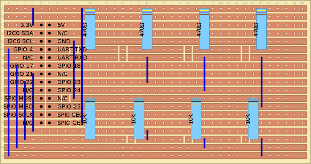
For this project, we need 19 copper strips, each with 37 holes.
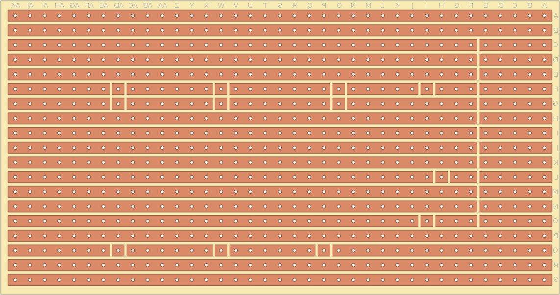
Click to see full size
The image shows the size we need. (Ignore the cuts in the tracks for now, we’ll come to those later).
So if you have a bigger piece than this, you can cut it down to size.
My preferred method for cutting veroboard is to score along the first row of holes I don’t need with a Stanley (or other craft) knife, and then snap. Alternatively, to cut a short length, you can just cut at either end of the row with a pair of side-cutters and the board will snap. You might like to try this a few times before cutting down to final size.
Once we have cut the board down to size, we need to cut the tracks that we don’t want to be joined.
Refer to the diagram above again – you will need to count very carefully and I recommend marking the tracks to be cut on the copper with a marker pen and checking and re-checking before you cut!
Where a cut is shown on both sides of a hole, the entire copper around that hole can be easily removed using a spot face cutter or drill bit. Simple insert the cutter or bit point into the hole and rotate by hand while applying light pressure. You may want to practice on a spare piece of board.
Where a cut is required between two holes, this is more tricky. You need to cut with a Stanley knife very close to each hole. The copper strip in between the cuts can then be scraped off with a hot soldering iron, which melts the glue bonding it to the board.
Step 2 – Fitting the wire links
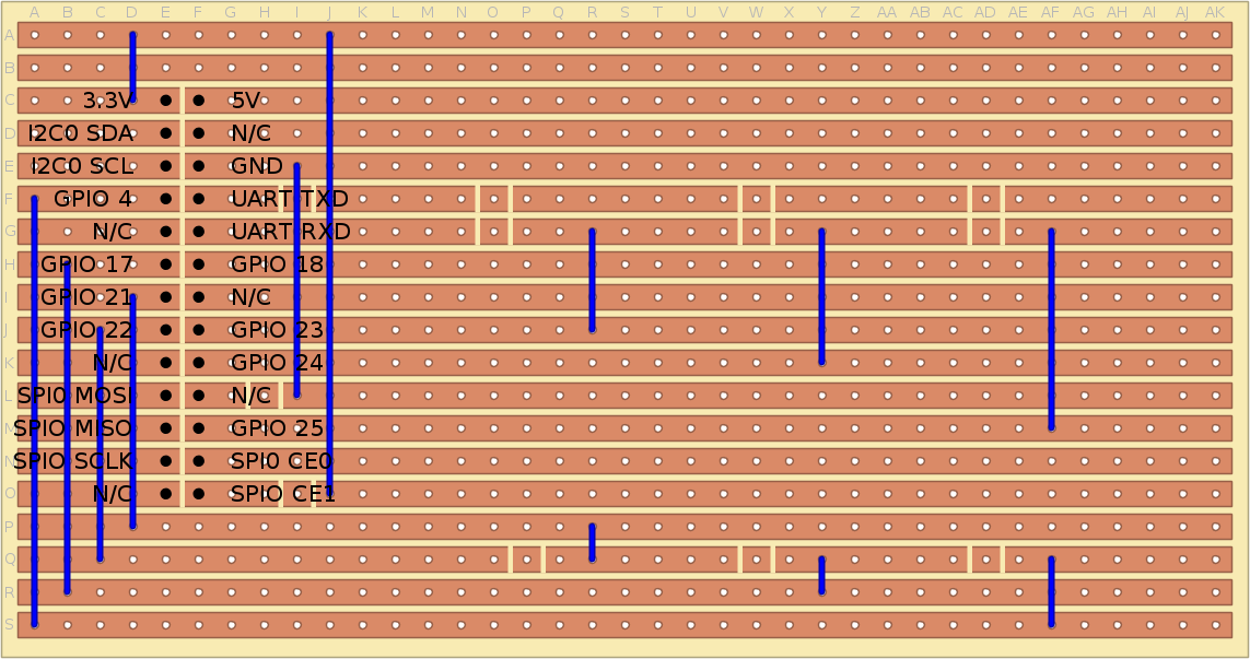
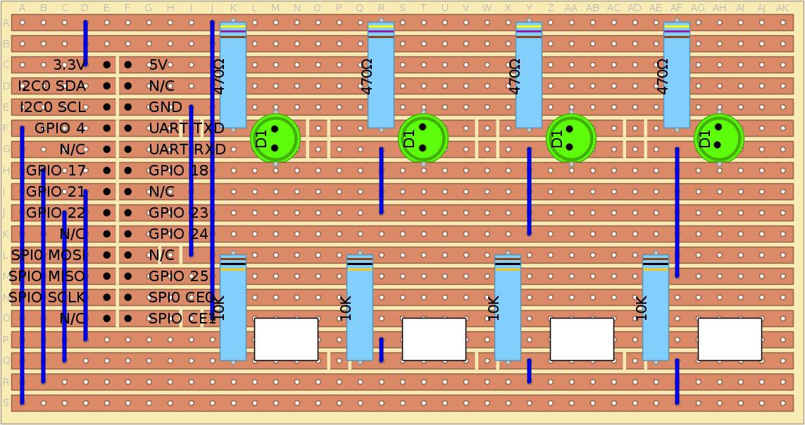
Click to see full size
Now turn the board over so you can no longer see the copper.
All of the diagrams throughout the rest of the article show the board viewed from the top, although the tracks and cuts are still shown for reference.
To fit the wire links, simply cut a length of wire, strip about 4-5mm of insulation from each end, push each end through a hole, and solder on the other side.
I’m not going to give a detailed tutorial on soldering. There is a good Instructable here. One piece of advice I will give to get a good joint is to always solder in the following order:
- Place the iron tip on both parts to be joined, e.g. the wire and the copper strip
- Once the iron tip is touching both parts, start to feed solder into the joint, ideally to the copper track very close to but not touching the iron
- Withdraw the solder from the joint as soon as there is enough to secure the physical and electrical connection
- Withdraw the iron
Also, for safety’s sake, I advise that you ensure you are always working on a stable surface, you have an appropriate stand for your iron, and that you wear safety glasses and solder in a well-ventilated area. A fan to blow the fumes away from you as you solder is also a good idea.
We will now fit the rest of the components – the reason for following this specific order is to fit the tallest components last. If you fit the tallest components first, the shorter components will fall out of the board when you turn it upside down. This way you can lay the board flat on your work surface and the components you are soldering in will remain snug to the board.
Step 3 – Fit the resistors
Resistors can be fitted either way round, but it looks neater, and makes it easier to check the colour-coded values if you fit all resistors on a board the same way round.
Details of the resistor colour code can be found here, and there is a useful calculator here.
I have a handy trick to help with the bending of components to the right length when fitting. If you look at the resistors on this board, each of them needs to be bent so that one end is 5 hole spaces away from the other. If you cut the board following my advice earlier, you should have a rough edge with lots of “half holes” along the side of the board.
If you bend one leg of the resistor, and drop this through a hole in the board which is 5 hole spaces from the edge, you can then bend the other leg over the “half hole” on the edge of the board.
Step 4 – Fit the switches

Unfortunately, the stripboard design package I used (the excellent diylc) doesn’t have a symbol for the switch. In this diagram the rectangle show the positions of the switches, and the corner of each rectangle shows where a pin of the switch goes through the board.
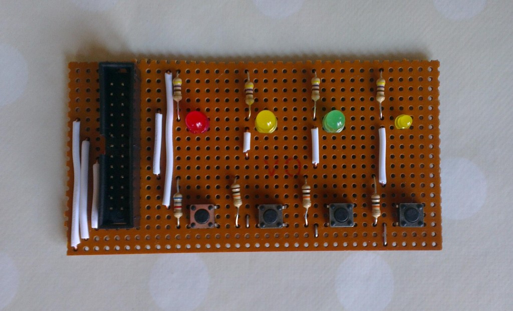
The photograph of the board is a better reference for the orientation of the switches.
Step 5 – Fit the LEDs and GPIO connector
I’ve put these two together because the LEDs I bought were about the same height as my GPIO connector.
Note that the LEDs must be fitted the correct way round. The LEDs will usually have one lead longer than the other, or a flat side on the LED body itself, or both. An LED, like all diodes, has two connectors, the anode (where the current goes in) and the cathode (where the current goes out). The longer lead identified the anode, and the flat side on the body identifies the cathode.
In this board all of the LEDs have the anode towards the top of the board.
So, if your LEDs have one lead longer than the other, put the longer lead at the top. If they have a flat side, put the flat side towards the bottom.
The connector, which is fitted so that the pins go through the holes marked with black spots in the diagram, must also be fitted the correct way round. There is a cut-out in the housing of the connector which must be towards the left looking at the board as shown above.
Again, the photograph shows a better view for orientation purposes, but ensure the pins locate directly by referencing the diagram.
That’s it, you’re done!
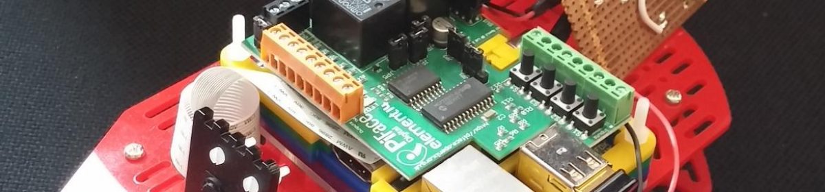
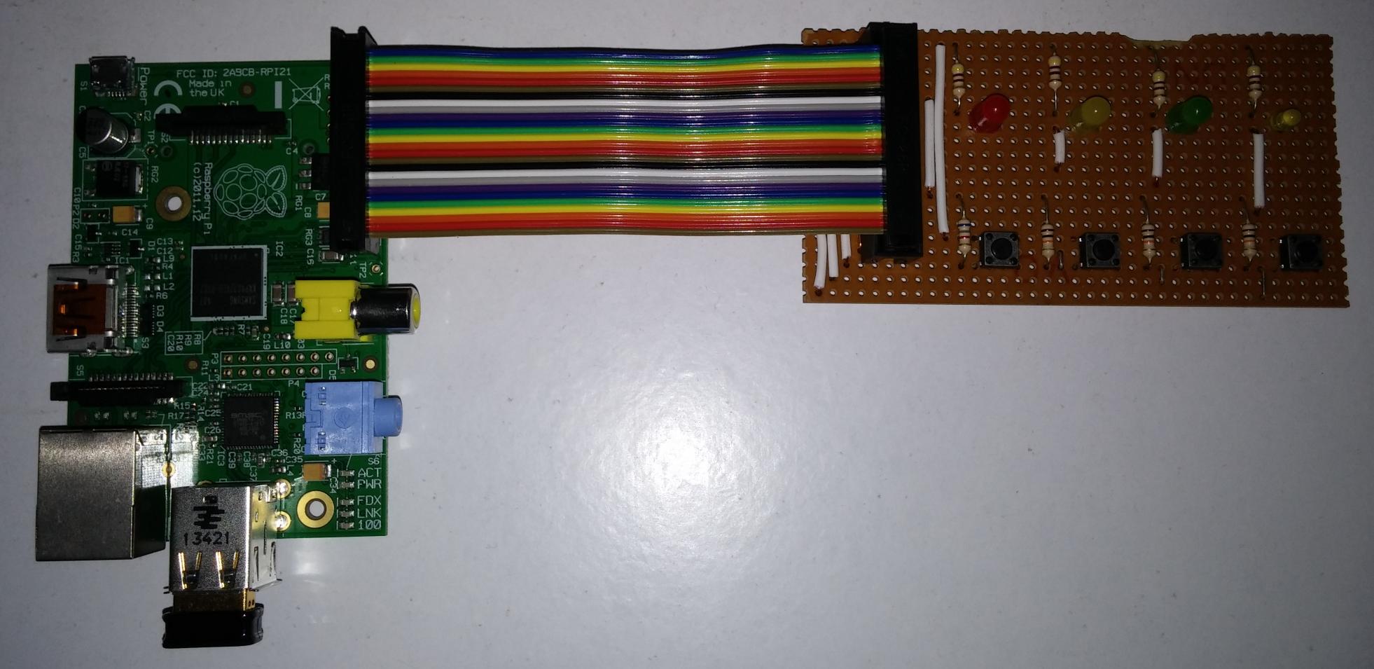
Connecting it to the Pi (which I recommend you do with the power off) is simply a matter of connecting the ribbon cable between the Pi and the PCB.
Like this:
Software
So, now you’ve built it, you just need to write some software!
If you want to use Scratch, I’ve written some instructions for that.
First you’ll need to install Simon Walters’ excellent ScratchGPIO from here.
You’ll need to download my Scratch script which initialises ScratchGPIO correctly for the PCB from here
Then you can follow my worksheets
If you’re planning to use python, or some other language, then you’ll need the GPIO pin numbers of the LEDs and switches, these are also provided in my Scratch worksheets.
Have fun!
One thought on “DIY Raspberry Pi GPIO LEDs and Switches board”