So, in part 1 and part 2, we’ve looked at the problem and how we might solve it. Now we’re going to choose which Arduino best fits our project and fit it into the keyboard!
I’ve already made my mind up to use one of the Arduino series of boards.
I do like the Arduino family of hardware – it’s open source, it has good library support, built-in serial I/O etc.
The question is, which Arduino do we need?
Which Arduino?
There are three options we can consider – mainly because I happen to have one of each of them in my drawer!
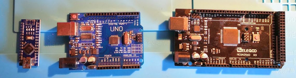
These three boards are, from left to right, the Nano, Uno and Mega.
(The links above are affiliate links to Amazon. If you are going to buy from Amazon anyway, and use my links, I might get a very small amount of money in thanks for the effort I put into the blog. No obligation!)
For most projects, the Uno has been by goto board. I’ve recently used the Nano for some very small projects, which I might get round to blogging about one day! I’ve used the Mega for one other project, which I should definitely get round to blogging about one day!
Here’s a quick comparison table of the three boards:
| Nano | Uno | Mega | |
| Processor | Atmega328 | Atmega328 | Atmega2560 |
| Clock speed | 16 MHz | 16 MHz | 16 MHz |
| Flash program memory | 32 KB | 32KB | 256 KB |
| EEPROM storage memory | 1 KB | 1 KB | 4 KB |
| RAM | 2 KB | 2 KB | 8 KB |
| Digital I/O pins | 14 | 14 | 54 |
| Analog inputs | 8 | 6 | 16 |
Deciding factors
I don’t think our project is going to need more than 32 KB of program memory. That may not seem like much when a Word document with nothing in it can be double that size but, trust me, it’ll be enough.
The deciding factor for us is likely to be the amount of I/O we need.
So, let’s have a look.
First, we have the keyboard – without stripping it all down and looking in detail at the circuit board we don’t know exactly how it connects, but we do know that it has a 20-pin ribbon connector to the current main board. Let’s assume, therefore, that we’ll need 20 digital I/O ports.
Now, turning to the control panel. We could count the buttons and LED segments, but it’s likely there is some multiplexing going on there, at least with the LEDs, so that’s not likely to help. Again, we can look at the connector size – it has 26 pins. Not all of those are digital, though. There is a master volume slider, pitch-bend and modulation wheels – they all use variable resistors, which will require 3 analog inputs.
The four dials I’m not sure about – they might be variable resistors, but they’re just as likely to be rotary encoders, which are digital. If we assume all the 26 connector pins are used, and we know we have between 3 and 7 analog inputs required, we could assume for simplicity that we therefore need between 19 and 23 digital I/O pins.
That makes a total of 39-43 digital I/O pins (but perhaps fewer) and 3-7 analog inputs.
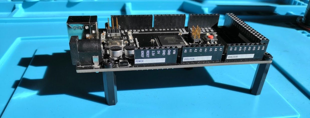
The Mega is the only option.
Adding the brain
The next question is – how will we fit it into the case?
First of all, we’ve decided that we want to be non-destructive as far as possible. Also, we’ve decided that in a later stage, when we’re confident about getting destructive, we want to retain the original “brain” PCB for its interfaces – they all fit nicely into the right place on the rear panel.
We need to bear these things in mind when we work out where and how to fit the board.
Looking at the space available, most of it is taken up by the control panel PCB, but there are clear areas on there that we might be able to attach to.
I have some plastic machine screws and pillars that we could use for this – if we glue the pillars to the control panel PCB in the right place, then we can screw the board to those, and easily remove it when we need to work on it.
Fixing in place
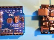
The easiest way to do this is to screw the pillars on to the Arduino, and then glue the pillars down to the control panel PCB. I’m using superglue – it holds fast, but if it goes wrong, the pillars are fairly easy to snap off.
So, we fit the pillars to the Arduino, apply glue to the other ends, hold in place for a minute, and then leave for 24 hours to cure fully.
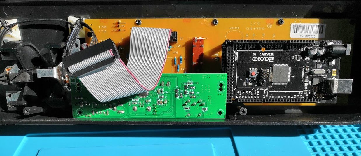
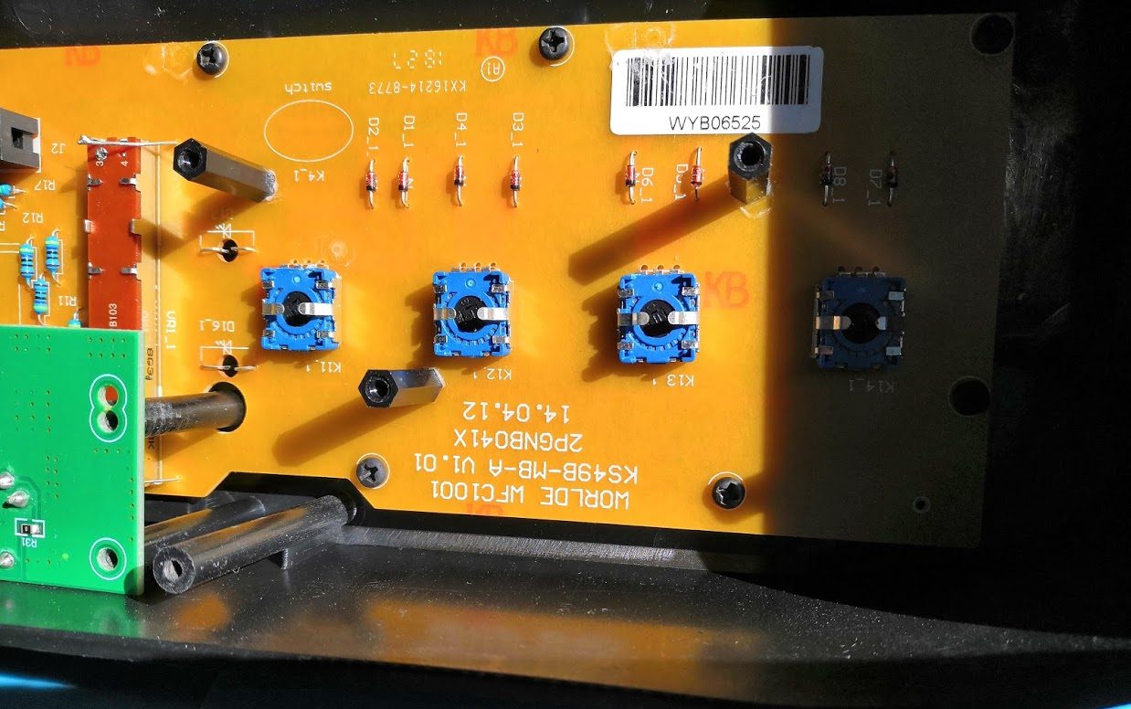
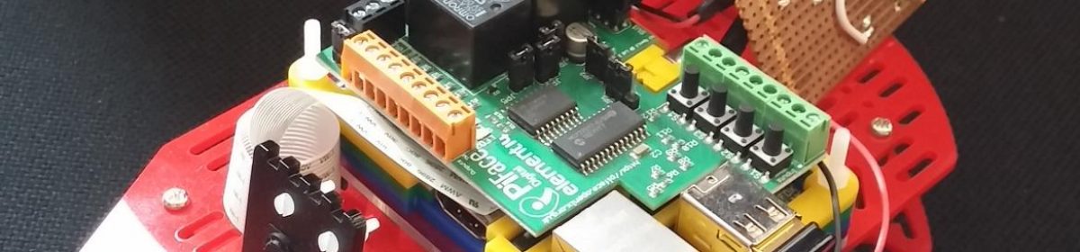
In the image above you can see the pillars in place with the Arduino removed. Also, towards the top edge of the brown PCB, you may be able to see some dried glue – this is from a previous attempt to fit the Arduino which interfered with the keyboard. The pillars were easy to snap off with a little force!
Now we’ve selected and fitted the brain, we can start actually doing some electronics and programming to bring this thing to life! That’s in part 4…