

In this post, we take a simple look at what I/O is, and why it exists in all systems. Then we look at the method of multiplexing which allows us to connect to it more efficiently, making the most of the pins available on a microcontroller.
What is I/O?
Input and output, or I/O, are critical to any project. Without them a computer or microcontroller would just sit there. You would have no way to ask it to do something, and it would have no way to tell you the result. A severe case of locked-in syndrome.
Taking the example of your home PC, because the tasks it can carry out are so varied, you need to be able to transfer many different types of information in a fairly human way, to and from the computer.
You may occasionally want to throw your QWERTY keyboard, mouse and monitor out of the window, but they are pretty effective for this task, generally.
However, your PC isn’t the only device which contains a computer of some kind. Look around your home and think about other devices and their I/O systems. Your microwave oven, for example, has inputs and outputs. Those buttons on the front, the dial for setting the weight or time are inputs. The display which shows you the weight you’ve selected, and then how much time is remaining, is an output.
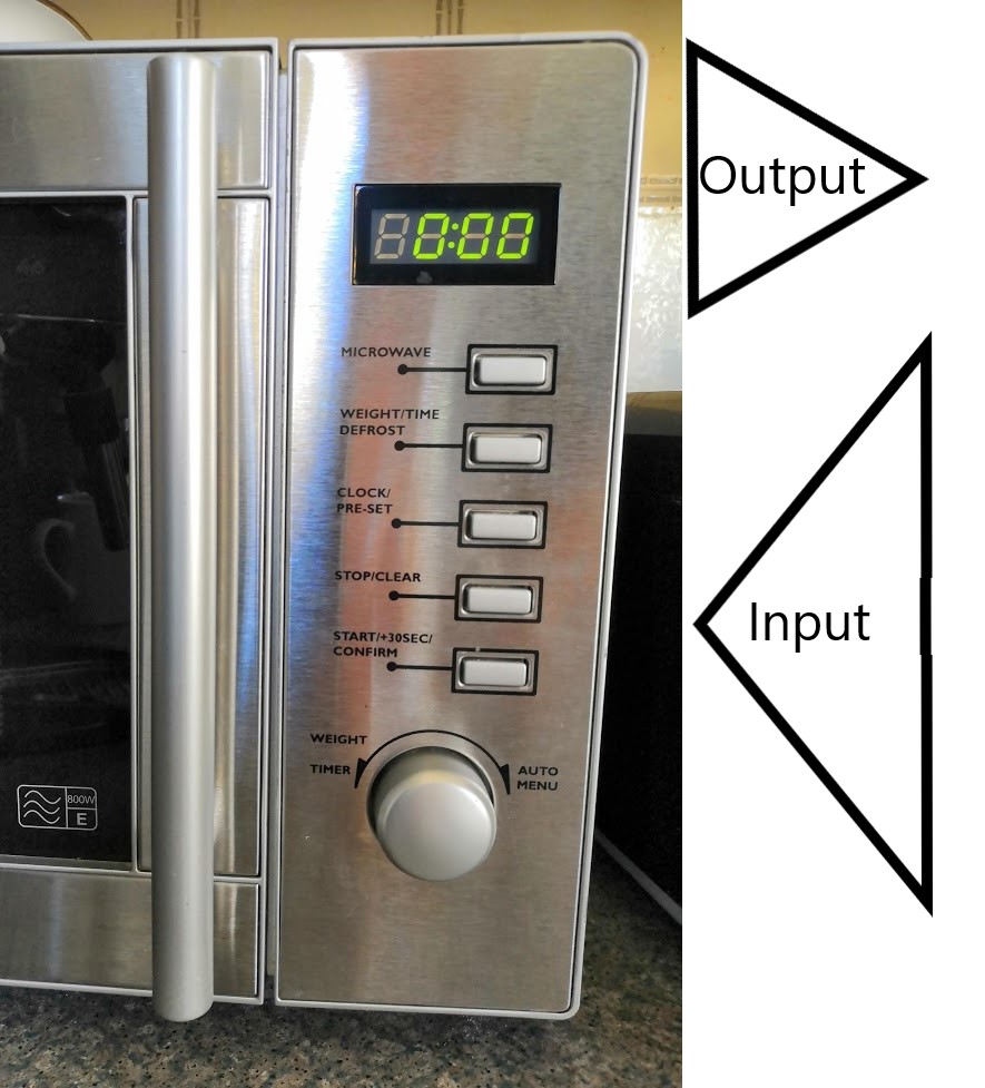
Of course, there’s also the output of the beep at the end which tells you your food is done!
Microcontroller I/O
As well as the I/O you can see, your microwave oven also knows when the door is open, controls the magnetron which cooks your food, and probably several other things inside the box that you can’t see.
Microcontrollers which live inside our domestic devices, then, need lots of different interfaces to our human world. These are connected to GPIO (or general purpose I/O) pins on the microcontroller chip itself.
For every piece of I/O, i.e. every button, every individual digit segment of those LEDs, the microcontroller needs to output a signal. If we did it the simple way, that would mean a pin on the chip for every piece of I/O. Also lots of wires between the chip and I/O device.
Looking at the timer display on our microwave, each digit has 7 segments, and then there is the colon in between. That makes a total of 29 LEDs, all of which need to be individually controlled by the microprocessor.
If we look at the example of the midi keyboard project on this blog, there are a total of 50 switches on the keyboard, 12 switches, 29 LEDs and 3 analog devices on the control panel. That’s a total of 94 I/O devices!
Fortunately, we don’t have to wire individually to each of those devices, and we don’t need an individual microcontroller pin for each. There are several ways to achieve this. Here we’re going to talk about multiplexing, one of the most common methods used.
Multiplexing LED outputs
Conventional LED wiring
Firstly, let’s talk briefly about what an LED is. It stands for Light Emitting Diode. A diode is a semiconductor device which only allows current to pass in one direction. Hopefully the “light emitting” part is fairly obvious!
Here is the circuit schematic symbol for an LED:
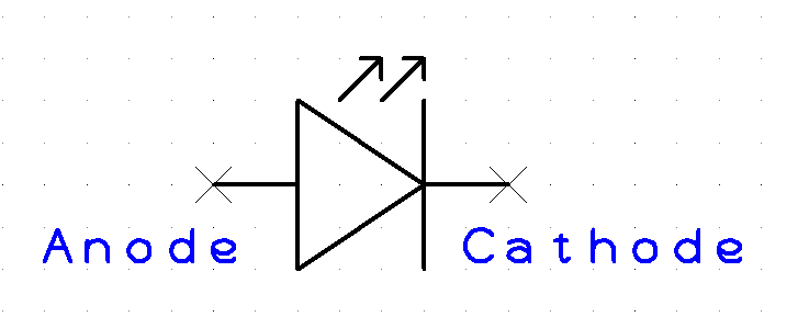
The current in an LED (in any diode in fact) flows from the anode to the cathode only. So if the voltage at the anode is higher than the voltage at the cathode, current will flow and the LED will light up. No current will flow under any other circumstances.
If we have, say, 16 LEDs to connect to our microcontroller we could do it the naive way. For example, we could connect all of the cathodes to 0V, and connect each of the anodes to GPIO pins. Then as we set each GPIO pin high, current will flow and that LED will light.
That would require 16 GPIO pins, and 17 wires (one for each GPIO, plus 0V) to be carried to our set of LEDs.
The multiplexing method
Multiplexing allows us to do this with only 8 GPIO pins and 8 wires.
It works like this:
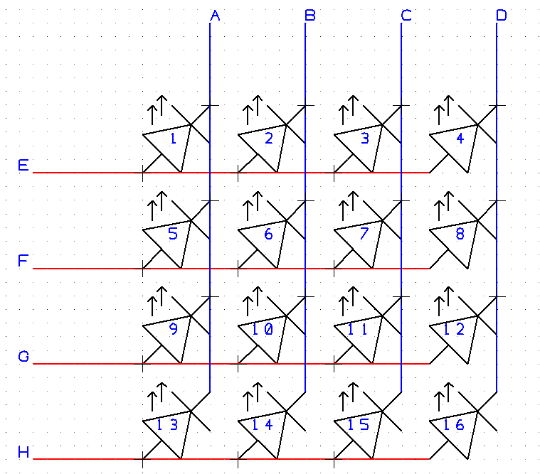
In the diagram above, we can see that each LED has its anode connected to one of four row inputs, labelled E to H. Each LED’s cathode connected to one of four column inputs, labelled A to D.
So, each LED will only light if both its anode is high and its cathode is low. For example, to light LED number 7, we need to make F high and C low.
We need to keep individual control of our LEDs, though. We don’t want numbers 5, 6 and 8 to light up just because 7 is lit! That’s easy, all we need to do is make sure that when F is high, A, B and D are also high. The LEDs won’t light if both their anode and cathode are high.
Similar logic applies to the columns, when we are setting C low to light LED 7, if we don’t want other LEDs to be lit, we need to make sure rows E, G and H are low, so that current doesn’t flow through LEDs 3, 11 and 15.
Multiplexing works by cycling through the rows very quickly, and for each row, setting the appropriate voltage on the columns so that only the LEDs we want in that row to be lit are lit.
So, with multiplexed LEDs, there will never be a time when LEDs from two rows are on at the same time, but it is done so quickly the human eye can’t tell.
Neat, huh? You can see how this would scale up – if we had 100 LEDs, we would only need 20 GPIO pins and wires to address them.
Multiplexing inputs
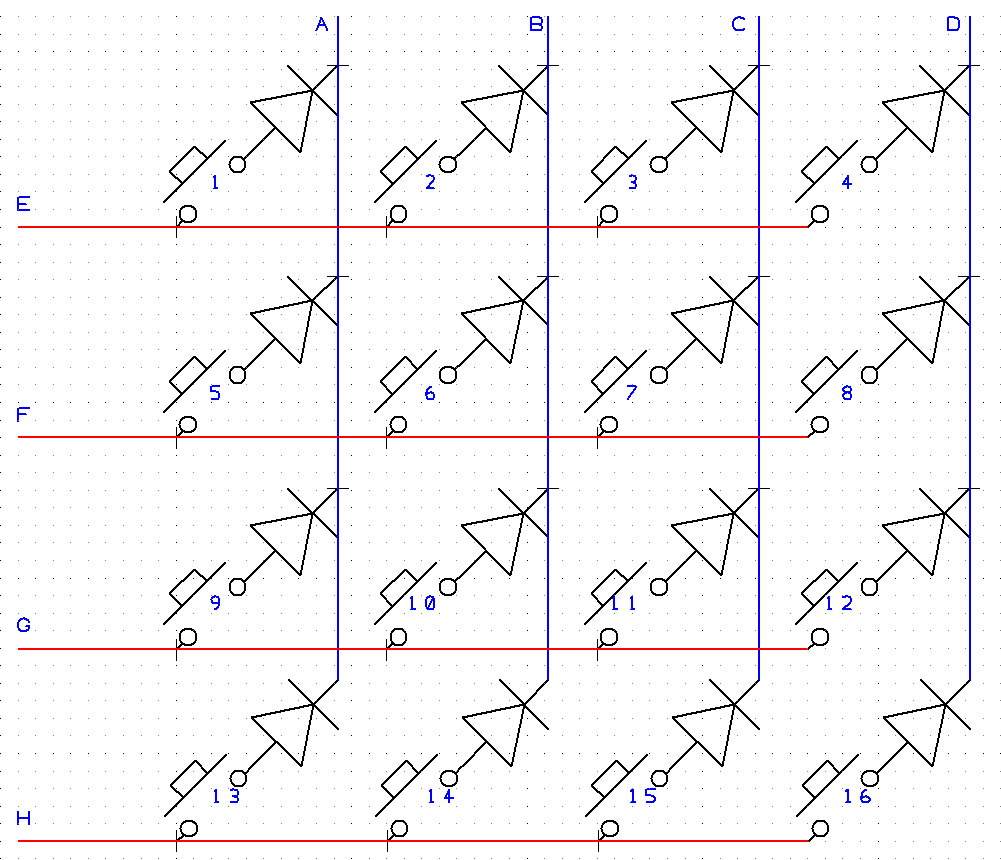
Similarly, we can multiplex inputs:
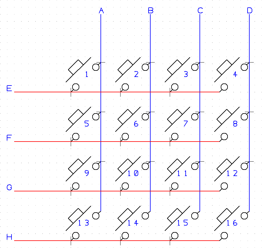
In this scheme, we connect rows E to H to output pins on the microcontroller and columns A to D to input pins. We then cycle through each row setting it high, and we check which columns are high.
For example, when we set F high, we will see column C go high if button 7 is pressed.
There is however a problem here. If, for example buttons 7, 11 and 12 are pressed together, when we set row F high, current will flow from F through switch 7 to column C, and then through switches 11 and 12 to column D, making it appear as though switch 8 is also pressed.
For this reason, we fit a diode in series with each switch, to prevent the back-flow of current, like this:
We didn’t have this problem with our LEDs because they already only allow current in one direction. If we’d been using conventional bulbs diodes would have been required there as well.
Summary
So, multiplexing, a great way to reduce the amount of wiring required and to make the most of however many inputs your microcontroller has.
Thank you SO MUCH for this!
Your content is a diamond in the rough.
I have searched high and low for a simple, beginners’ explanation of this concept.
I have all of the interest and excitement, and none of the know-how.
You are very appreciated, friend! Thanks for taking the time to write this up for a DIY-er like me!!!
You’re very welcome, Ben. I’m a DIYer myself. Fun isn’t it?