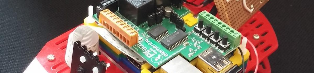
Now we’ve decided on our microcontroller, we can start connecting it to the hardware in the Midi Keyboard. We’ll start with… the keyboard.
Let’s finally play some music with this thing!
The keyboard has 25 keys, but there are only 20 wires in the ribbon cable connecting it to the main board. Clearly some kind of multiplexing is in use.
By using multiplexing, we can connect many inputs or outputs using much fewer wires and physical GPIO pins. I’ve written a separate post on this which explains in detail why it is used, and one popular method for achieving it.
Working out how to connect the keyboard
Our plan is to connect the 20-wire ribbon cable connector to our Arduino mega, somehow. First we need to understand how the keys translate to pins on that connector.
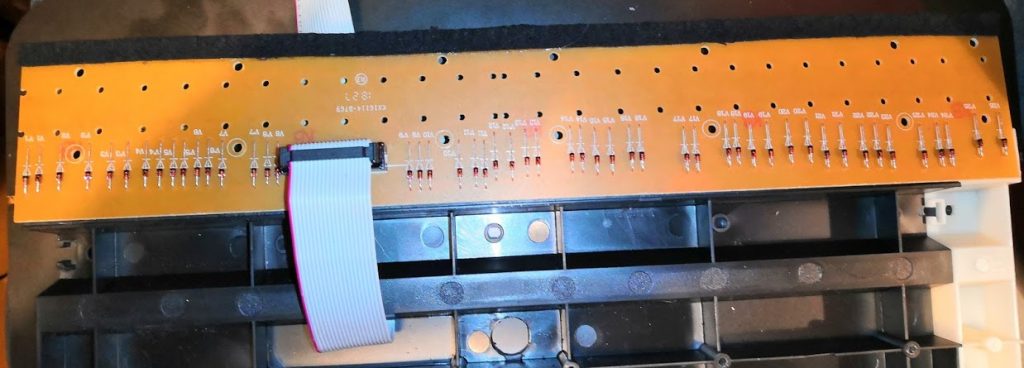
We’ll have to take the keyboard apart to find the other end of the keyboard cable. Then we have to painstakingly trace every connection to its source.
I’m not going to bore you with how long that took!
The black pads on the PCB below are the switch contacts which the piano keys press on. Each of these contacts has two sides which are connected together when the key is pressed.
Note that there are two of these per key, rather than just the one per key which I’d expected to find. We’ll come to why that is in a later post. For now it’s important to note that the keys strike the PCB in such a way that the uppermost contact is hit first, slightly before the lower one.
Multiplexing – how are the keys arranged?
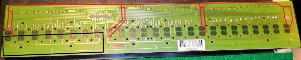
The image above shows a good physical example of multiplexing theory. We can see from the black box how the bottom side of all of those contacts are connected together. Let’s call this a “row”. Helpfully, the PCB manufacturer has labelled the rows for us: 1, 3, 5 and 7. The row above each of these we can safely number 2, 4, 6 and 8. Note how each of rows 1-6 contains 8 switches, but rows 7 and 8 contain only one each.
The red lines show how the top sides of a particular switch from each row are connected together. This is an example of a column.
So, all we need to do is connect each of these rows and columns to our Arduino, and detect when a row and column are connected together. We’ll know that key has been pressed and can then send the appropriate MIDI message. When the computer (or other instrument) receives the message it plays the note.
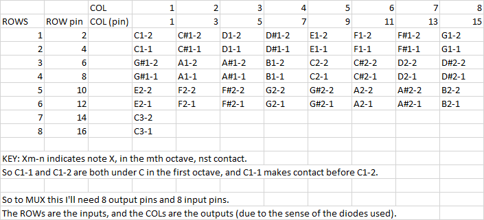
Eventually, having traced all the tracks I identified which notes were in each row and column. The table below shows which pin numbers those connected to on the header:
Keyboard multiplexing in practice
So, all we need to do now is connect the rows and columns directly to our Arduino GPIO pins (rows are inputs to the Arduino, columns are outputs – this is governed by the direction of the diodes in the circuit).
Then we just write a simple bit of code which does this:
- Switch off the columns except #1
- Check all the row inputs
- Cross reference with row #1 in the table above to identify which keys have been pressed or released since last time, and send a MIDI command to switch that note on or off
- Switch off the current column, and switch on the next one
- Go back to 2
Here’s our input circuit:
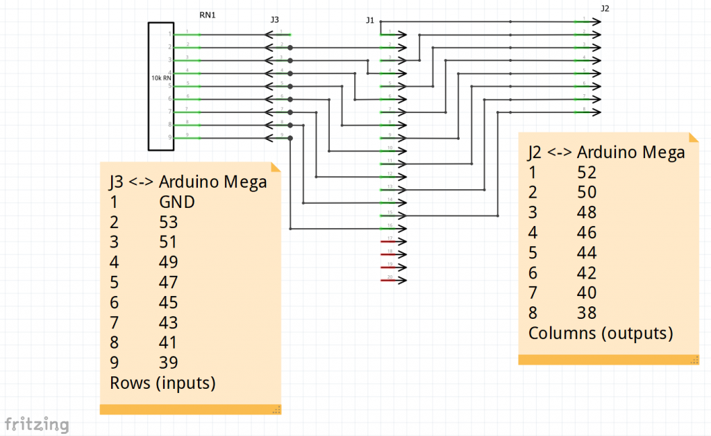
J1 is where the keyboard ribbon connector plugs in, while J2 and J3 are connectors which will sit in the headers on the Arduino, connecting it all together.
RN1 is a resistor network. This contains 8 resistors which are used for “pull-down” – making sure that when nothing is connected to them (i.e. if a key isn’t pressed) they appear as 0V or a logic LOW on the input. When a key is pressed, if the appropriate column is turned on at the time, the input at the row will appear as 5V, or a logic HIGH. Without the pull-down resistors, the inputs will have a tendency to “float” when nothing is connected to them, and we are likely to see phantom keyboard-presses if we allow this to happen.
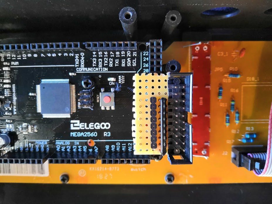
Here is a picture of the board plugged in to the Arduino. To get it as small as this, I had to get a bit creative with my construction techniques, including cutting a section out of the header which with ribbon plugs into, to fit the resistor network on the board.
Software implementation
Here is the code which runs on the Arduino – on github.
It’s actually fairly simple, only 61 lines, but here are some key hints:
- We are using a MIDI library provided for Arduino by FortySevenEffects to send Midi messages
- The setup() function is run automatically by Arduino every time it is powered up, and sets up the I/O, telling the Arduino which pins to use as input, and which as output
- The loop() function is run repeatedly, and performs the steps we outlined above.
- It cycles through the columns, setting each one active, and reading the rows
- This data is built into an array called switch_states which contains the current state of every keyboard switch
- It compares this array with the previous version, old_switch_states, so that it can see which keys have been pressed, and which released
- For keys which have been pressed, it sends a midi NOTE_ON message with a velocity of 64, to start the note
- For keys which have been released, it sends a midi NOTE_ON message with a velocity of 0, to stop the note
We discussed the use of NOTE_ON to both start and stop notes in the MIDI explainer post.
MIDI connection
So, we are reading the notes from the keyboard, and our Arduino is sending MIDI messages, but where are they going? Well, nowhere unless we connect them to an instrument!
For testing, we used a cheap MIDI to USB interface. These are widely available on ebay, and provide both MIDI-in and MIDI-out plugs. These allow the PC to be connected either to a controller (like our keyboard) or an instrument (like an external synthesiser).
So, we just need to provide a standard 5-pin DIN MIDI connection. You can see this in the video below if you look closely, but it is two connections:
- a 220R resistor connected between the MIDI output pin (TX1 on the Arduino) and pin 4 of the DIN socket
- a wire connected between GND on the Arduino and pin 2 of the DIN socket
This isn’t a very robust MIDI out circuit, but it works, and we’ll improve it later.
See more details about the electrical connections for MIDI in the Sparkfun MIDI tutorial.
If this all seems a bit scary, or you don’t have a MIDI to USB interface, it is possible to send our MIDI messages through the Arduino’s USB port. See my simple guide here.
Success!
Anyway, here is the result. Using the excellent online MIDI synthesiser, the Virtual Piano, a demonstration of my poor music skills but, more importantly, a working Arduino MIDI keyboard!
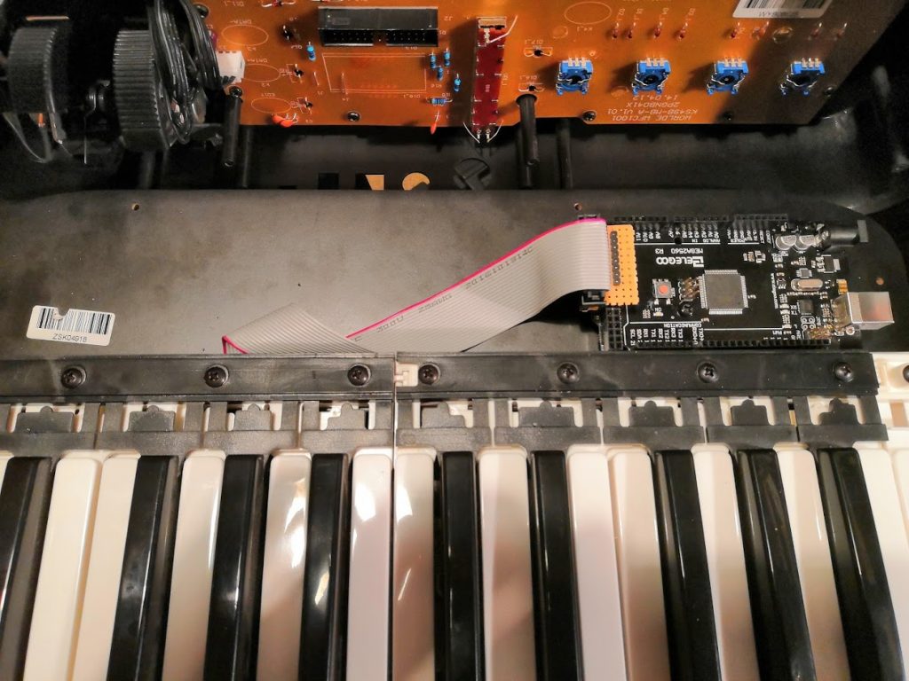
…and some rework
Once we fitted the keyboard header on top the Arduino, we could no longer put the control panel cover back on, so ended up snapping off those PCB mounting pillars and moving it somewhere else. The lesson, remain flexible!
What next?
In the next instalment, we’ll connect the control panel, and start replacing all those fancy MIDI functions.
One thought on “Arduino Midi Keyboard part 4 – Reading the keyboard”