
So, we’ve got as far a working keyboard, which can send MIDI messages to an instrument or a PC, including via USB. If we think back to part 1, though, we had that before we started the project! The whole point was that the additional features didn’t work correctly. Let’s make a start on them by connecting up an Arduino control panel adaptor.
Here we go again!
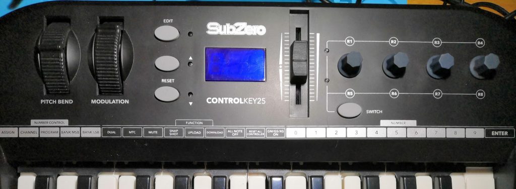
This is a very similar job to connecting the keyboard. First, we need to look at how the control panel was connected to the previous main board, and then trace all the tracks on the control panel’s circuit board to find out how they are connected.
We’re going to work out how everything connects to the ribbon cable which plugs into the control panel board, so we need to ensure we accurately understand the pin numbering for this connector. Fortunately, this website can help there.
Completing that exercise reveals the following:
- The four rotary controls on the right-hand side of the panel are rotary encoders rather than potentiometers. These are neat little devices which act like a potentiometer, except that they can be turned forever in either direction. Also, rather than producing a variable resistance, they instead have two switches which repeatedly close and open as the dial is turned. On indicated clockwise motion, the other anti-clockwise.
- Unsurprisingly, the rotary controllers and the other switches are multiplexed in a similar way to the keyboard.
- The digital LED display is a multiplexed common-anode arrangement, where there is a cathode (negative) connection for each segment, and an anode (positive) connection for each digit.
- The master volume slider, and pitch-bend and modulation wheels, are potentiometers
How are these things connected?
So, if we think back to how multiplexing works, we can easily connect the first three of these things with some digital inputs and outputs.
The two tables below are another way of representing how inputs and outputs can be multiplexed. This can be simpler than trying to read a schematic.
| Rows | Pin 1 (MUX output) | Pin 2 (MUX output) | Pin 8 (MUX output) | Pin 10 (MUX output) | Pin 12 (MUX output) | Pin 14 (MUX output) |
| Pin 5 (MUX input) | DATA- | SWITCH | R4 clockwise | R3 clockwise | R2 clockwise | R1 clockwise |
| Pin 7 (MUX input) | DATA+ | EDIT | R4 anti-clockwise | R3 anti-clockwise | R2 anti-clockwise | R1 anti-clockwise |
To read these switches, we will connect 2 output pins from the Arduino to pins 5 and 7, and 6 input pins from the Arduino to pins 1, 2, 8, 10, 12 and 14. Our software will then need to cycle the outputs to pins 5 and 7, and read the 6 input pins. If we see, for example, an output on pin 1 when we have an input on pin 5, that means that the DATA- button has been pressed. However, if we see it when we have an input on pin 7, then the DATA+ button has been pressed.
Testing the connections
Later, we’re going to build some permanent circuitry to connect the 26-way ribbon connector to the Arduino. This will be similar to what we built for the keyboard, but probably more complex. It would therefore be sensible to test our analysis so far before we do that, because it might be difficult to modify it if it’s wrong.
The DATA+/DATA- buttons we mentioned above have quite a simple function in the keyboard’s normal playing mode. They switch the keyboard’s octave up and down.
If you’ve looked at the code from last time, you may have noticed that every MIDI note we send is calculated from a baseline defined here:
const int middleC=0x30;So, this should be fairly simple. All we need to do is make that not a “const” so that we can change the value, and increase/decrease it by 12 (the number of semitones in an octave) when DATA+/DATA- is pressed.
That should be easy, and a good test.
So, to just test these two switches, it’s a fairly simple bit of wiring! Or so you would think – when I first tried it, the octave changed randomly. For some reason, in spite of needing pull-down resistors for the keyboard inputs, it didn’t occur to me I would need them again here! Without them fitted, the input voltages float around and cause phantom button presses.
With them fitted, and the Arduino code updated, here’s the result:
So, now we know our wiring for the octave buttons works, we’re confident that our analysis was good, we can move on to a permanent fixture.
LED connections
Similar to the multiplexing for the switches, the review of the control panel circuit board revealed a multiplexed arrangement for the LEDs.
| Pin 15 (MUX anode) | Pin 16 (MUX anode) | Pin 22 (MUX anode) | Pin 24 (MUX anode) | |
| Pin 17 (MUX cathode) | R5-R8 indicator | Digit 1 segment e | Digit 2 segment e | Digit 3 segment e |
| Pin 18 (MUX cathode) | EDIT mode indicator | Digit 1 segment a | Digit 2 segment a | Digit 3 segment A |
| Pin 19 (MUX cathode) | R1-R4 indicator | Digit 1 segment d | Digit 2 segment d | Digit 3 segment d |
| Pin 20 (MUX cathode) | Digit 1 segment f | Digit 2 segment f | Digit 3 segment f | |
| Pin 21 (MUX cathode) | Digit 1 dp | Digit 2 dp | Digit 3 dp | |
| Pin 23 (MUX cathode) | DATA- indicator | Digit 1 segment c | Digit 2 segment c | Digit 3 segment c |
| Pin 25 (MUX cathode) | Digit 1 segment g | Digit 2 segment g | Digit 3 segment g | |
| Pin 26 (MUX cathode) | DATA+ indicator | Digit 1 segment b | Digit 2 segment b | Digit 3 segment b |
The segments a-g, and “dp” referenced above relate to a standard layout of a seven-segment digit, as below:
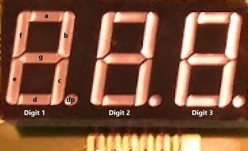
So, if we wanted to display the digit “1” on Digit 1, we would need to light segments b and c. Therefore, when pin 16 (the anode for Digit 1) is high, we will need to have pins 26 and 23 (the cathodes for segments b and c) low, and all the other segments high. That means current will only flow from anodes to the cathodes of the correct segments, and only those segments will light.
The final countdown connections
Finally, we need to know a few more connections on the 26-way ribbon:
| Pin | Function |
| 3 | Vcc (5V) |
| 4 | GND (0V) |
| 9 | Pitch bend potentiometer output |
| 11 | Modulation potentiometer output |
| 13 | Master volume potentiometer output |
The potentiometers, or variable resistors, are connected with 5V at one end, and 0V at the other end. When the sliders or wheels are moved, the voltage output varies between 0V and 5V, so all we need to do is measure that voltage. This means we need to connect these to analog input pins on the Arduino.
So, now we know everything we want to connect to our Arduino, we can design the little board that will allow us to do it.
Getting board?
To keep things simple, we’re going to base our board on this stripboard shield project, extended slightly to make use of some of the additional pins on the Arduino Mega.
Because of the layout of the 26-way connector, and the layout of the Arduino Mega, we want to think about how best to orient the connector to get the pins which we want to connect near each other – this will avoid unnecessary wiring on the breadboard.
Now, we know that the potentiometer outputs, pins 9, 11, 13, need to be connected to analog input pins. The analog input pins are all on one side of the Arduino, and pins 9, 11, 13 are all on one side of the connector – so it seems best to have these close to each other.
Also, apparently, it is possible to use spare analog inputs as digital I/O on an Arduino, so we should be able to make good use of the rest of the inputs on that side and come up with a sensible design for the Arduino Control Panel adaptor.
Useful additions
We’ll add a couple of other useful items to this board. Fitting a RESET switch for Arduino is helpful, because our board will cover the original one. Also, we’ll fit a 3-pin header which in future we’ll connect to our MIDI output port.
Here’s the final design.
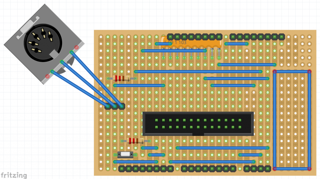
Because I’ve covered stripboard construction before I won’t deal with it again here. While Fritzing is a decent tool for breadboard design, it does have one slight failing. Although we can hide all the component layers so we can see where the cut tracks should be, the image can only be viewed from the top, but the tracks are on the bottom. I can’t find a way to reverse it in Fritzing – my solution was to take a screenshot and mirror that in another image editor.
Quite a neat job…
…though I do say so myself!
Finally, here’s the Arduino Control Panel adaptor board in place, alongside the keyboard connector, and with both ribbon cables connected.
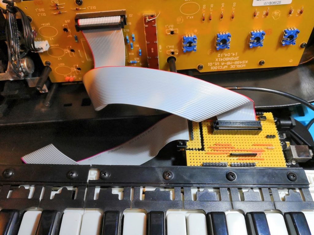
Other than the convenience of rear connectors, the hardware is now complete! We have everything we need to implement all the remaining features in software.