

A little over a year ago I bought a cheap (£40) 25-key midi keyboard. This post describes a problem with the keyboard, and my failed attempts to fix it. Then we hatch a plan to solve it by hacking in an Arduino.

I have never had much time to play with it. When I have, I’ve always found it hard to follow the instructions for the more complex functions.
They never seemed to work.
Finding the problem
Now, during Covid-19 lockdown, I’ve finally had chance to have a good play with it, and discovered why.
Helpfully, somebody has created a youtube video which explains the exact problem I’m having:
So while the general functionality of the keyboard works, it isn’t possible for any of the parameters to be set in EDIT mode. The keys in the higher octave which are supposed to represent numbers in that mode simply don’t work.
I began to play a little more, and discovered that those number keys seem to have functions of their own.
That led me to think that perhaps the key mapping was somehow wrong, i.e. the number keys were taking on the functions that should be in the lower octave. Perhaps they had somehow been swapped?
Digging deeper
I experimented with this using a very handy tool called Pocket Midi (Windows/Mac only, sadly). This tool allows monitoring of the midi messages being sent by a device when connected to a PC.
I discovered that when pressing one of the keys, lots of hex bytes with the value 0xFE were sent. According to SparkFun’s excellent Midi tutorial, those messages relate to a Midi function called “Active Sense”. This sends a keep-alive message, to confirm that the device is still connected.
There are three models of this keyboard, with 25, 49 and 61 keys, and they all share an instruction manual. Reviewing the manual, I discovered that a different model of the keyboard, the ControlKey49, with a 49 key keyboard, supports the “Active Sense” function, but that my humble 25-key model did not, and then I began to smell a rat! Did my keyboard somehow contain the incorrect firmware, or was there perhaps a link somewhere on a circuit board which tells the firmware which keyboard it is in?
My suspicions were confirmed, when I compared the functions I was pressing with the function layout on a 49-key model, here:

They keys I was pressing correlated exactly with the positions of the keys on the 49-key model.
Can we fix it?
Great! I thought. All I need to do is find out how to tell this thing that it’s a 25-key rather than 49-key model.
After a lot of searching, I found no PCB links which might do this, or evidence of any official firmware update, or even updating tool, so I started to dig more deeply.
Unsurprisingly, a device like this contains a lot of I/O, but not much else in terms of components. It’s very simple really – it reads a collection of buttons and potentiometers, displays some feedback on a small LED display, and converts all of that into MIDI messages which it sends out through a UART.
The main board is very small, just over 5″ x 1.5″, and other than a small voltage regulator (on the other side), and some connectors, contains just a few components and the small black chip you can see on the picture.
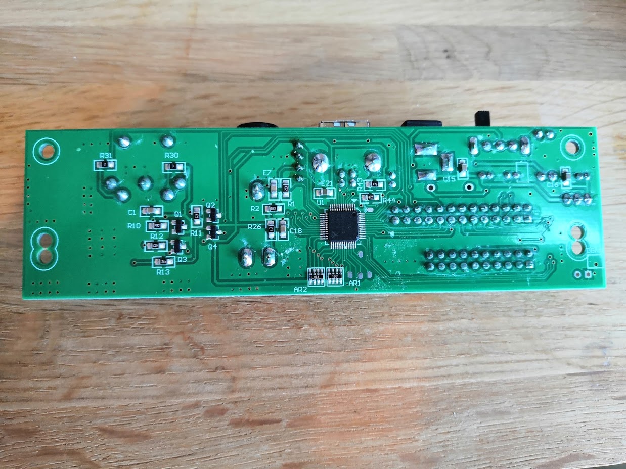
Arduino to the rescue?
This chip is an EFM8UB2, a micro-controller based on Intel’s venerable 8051 architecture. I’ve never come across one of these before, but did find some useful information (PDF) on the www.silabs.com website. However, all of the development tools are proprietary, and expensive. The chips use an interface similar to JTAG, called C2, and I thought through this interface there might be a way I could download the firmware from the chip, disassemble it, find out where the map is which tells it which function to find on which key in its special EDIT mode, and then correct it for my keyboard. Mad? Possibly, but it felt like a good lockdown project that might take a weekend.
Anyway, to cut a long story short, in spite of some very helpful code on github which, with an Arduino and a bit of fiddling, did allow me to communicate with the chip via its C2 interface, I determined that the chip seems to be read-protected. Oh, I guess that’s it then.
Not so fast! Given that as I’ve said, it’s a pretty simple device, why not replace the brains of the thing with an Arduino Mega? I can stick one in there, attach all the I/O to that rather than to the built-in board, and write my own firmware to do the job of the main board. Madder? Almost certainly. This is no longer feeling like a weekend project!
I’ll start to describe that in part 2!