In this post, I share some details of how Pisaac is constructed.
The Chassis
As I mentioned in my earlier post, my Raspberry Pi robot, “Pisaac”, is based on the Dagu Magician 2WD robot chassis.
I won’t go into the details of construction here, as it came with good instructions and wasn’t difficult to build. If you want to read the instructions before you buy, they are available here.
Some versions of this chassis come with a rotating castor, some come with a steel ball with free movement in all directions. I think the latter would work best, and that is the version I have. A rotating castor might suffer from a “shopping trolley” effect.
The chassis is basically two panels held apart by five metal hex spacers, which makes for rigid construction, and comes complete with geared motors and a battery holder for 4-AA cells.
The battery holder caused me the only issues I had during construction of the chassis, as the fixing screw holes are too close to the sides, and the sides had to be cut away to allow the screws to fit. However, I won’t be using the battery holder to power my final design, I just used it to test the chassis worked.
Note that there are also 4-wheel drive versions of this chassis, and while you might think “more is better”, I think for this application the 2WD version is better-suited. I am planning to drive the motors so that to steer one wheel goes forwards while the other goes backwards, which will allow Pisaac to turn in place. The 4WD drive versions have quite a long wheelbase, and neither of the pairs of wheels has any kind of steering mechanism, so I’m not sure how effectively they would steer.
Adding the “Brains”
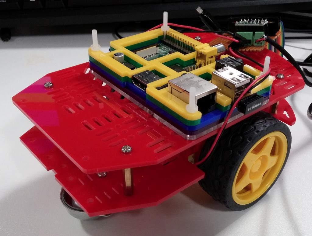
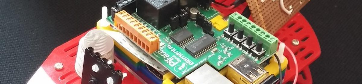
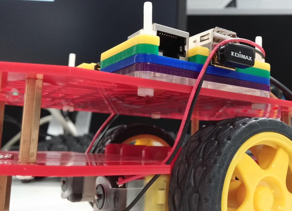
To fix the Raspberry Pi to the chassis, I used the excellent, versatile Pimoroni Pibow. I didn’t use all the layers, as I want to retain access to the internals and be able to fit other components on top, so I have used the bottom five layers and passed the nylon screws through holes in the top panel of the chassis and then the layers of the Pibow, as the images show.
The Raspberry Pi is built into the Pibow at the appropriate point as the layers are built up.
So now I have a chassis with motors, and the Raspberry Pi fitted on top. In the next couple of posts, we’ll move on to I/O expansion and motor control and get this thing moving!